CLASSICAL MECHANICS PART 1 : CARTESSIAN , CYLINDRICAL, POLAR COORDINATES AND ROTATIONAL FRAME OF REFERANCE
THE FOLLOWING CONTENT WILL COVER COMPLETE BASIC KNOWLEDGE ABOUT CLASSICAL MECHANICS AND GIVE YOU AN OVERVIEW ABOUT COORDINATE SYSTEMS AND FRAME OF REFERANCE......


Cartesian coordinate system
In three dimensions, three mutually orthogonal planes are chosen and the three coordinates of a point are the signed distances to each of the planes.[5] This can be generalized to create n coordinates for any point in n-dimensional Euclidean space.
Depending on the direction and order of the coordinate axes, the three-dimensional system may be a right-handed or a left-handed system. This is one of many coordinate systems.
Polar coordinate system
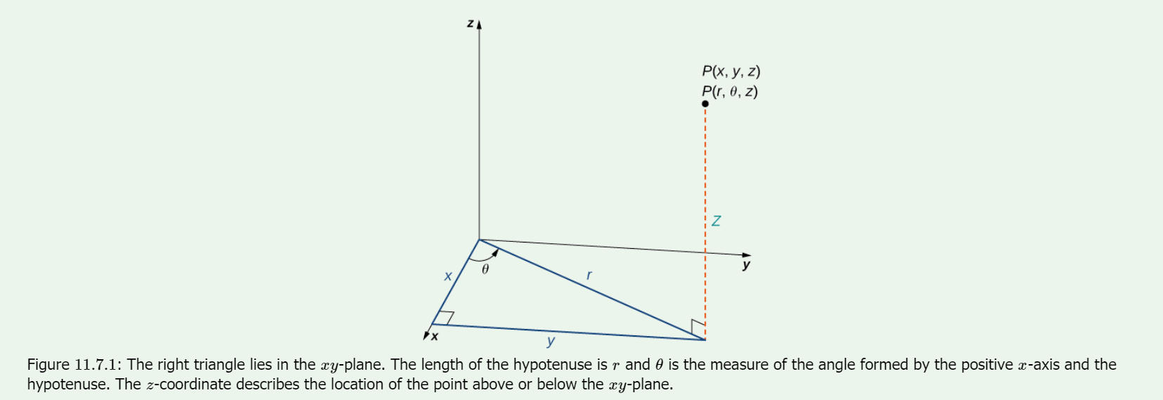
Cylindrical Coordinates
When we expanded the traditional Cartesian coordinate system from two dimensions to three, we simply added a new axis to model the third dimension. Starting with polar coordinates, we can follow this same process to create a new three-dimensional coordinate system, called the cylindrical coordinate system. In this way, cylindrical coordinates provide a natural extension of polar coordinates to three dimensions.
In the cylindrical coordinate system, a point in space (Figure ) is represented by the ordered triple where
- are the polar coordinates of the point’s projection in the -plane
- is the usual -coordinate in the Cartesian coordinate system
Conversion between Cylindrical and Cartesian Coordinates
The rectangular coordinates and the cylindrical coordinates of a point are related as follows:
These equations are used to convert from cylindrical coordinates to rectangular coordinates.
These equations are used to convert from rectangular coordinates to cylindrical coordinates
Spherical Coordinates
In the Cartesian coordinate system, the location of a point in space is described using an ordered triple in which each coordinate represents a distance. In the cylindrical coordinate system, location of a point in space is described using two distances and and an angle measure . In the spherical coordinate system, we again use an ordered triple to describe the location of a point in space. In this case, the triple describes one distance and two angles. Spherical coordinates make it simple to describe a sphere, just as cylindrical coordinates make it easy to describe a cylinder. Grid lines for spherical coordinates are based on angle measures, like those for polar coordinates.
Definition: spherical coordinate system
In the spherical coordinate system, a point in space (Figure ) is represented by the ordered triple where
- (the Greek letter rho) is the distance between and the origin
- is the same angle used to describe the location in cylindrical coordinates;
- (the Greek letter phi) is the angle formed by the positive -axis and line segment , where is the origin and
Converting among Spherical, Cylindrical, and Rectangular Coordinates
Rectangular coordinates , cylindrical coordinates and spherical coordinates of a point are related as follows:
Convert from spherical coordinates to rectangular coordinates
These equations are used to convert from spherical coordinates to rectangular coordinates.
Convert from rectangular coordinates to spherical coordinates
These equations are used to convert from rectangular coordinates to spherical coordinates.

These equations are used to convert from spherical coordinates to cylindrical coordinates.
Convert from cylindrical coordinates to spherical coordinates
These equations are used to convert from cylindrical coordinates to spherical coordinates.
Frame of reference
Non-inertial frames
Here the relation between inertial and non-inertial observational frames of reference is considered. The basic difference between these frames is the need in non-inertial frames for fictitious forces, as described below.
An accelerated frame of reference is often delineated as being the "primed" frame, and all variables that are dependent on that frame are notated with primes, e.g. x′, y′, a′.
The vector from the origin of an inertial reference frame to the origin of an accelerated reference frame is commonly notated as R. Given a point of interest that exists in both frames, the vector from the inertial origin to the point is called r, and the vector from the accelerated origin to the point is called r′. From the geometry of the situation, we get

Taking the first and second derivatives of this with respect to time, we obtain


where V and A are the velocity and acceleration of the accelerated system with respect to the inertial system and v and a are the velocity and acceleration of the point of interest with respect to the inertial frame.
These equations allow transformations between the two coordinate systems; for example, we can now write Newton's second law as

When there is accelerated motion due to a force being exerted there is manifestation of inertia. If an electric car designed to recharge its battery system when decelerating is switched to braking, the batteries are recharged, illustrating the physical strength of manifestation of inertia. However, the manifestation of inertia does not prevent acceleration (or deceleration), for manifestation of inertia occurs in response to change in velocity due to a force. Seen from the perspective of a rotating frame of reference the manifestation of inertia appears to exert a force (either in centrifugal direction, or in a direction orthogonal to an object's motion, the Coriolis effect).
A common sort of accelerated reference frame is a frame that is both rotating and translating (an example is a frame of reference attached to a CD which is playing while the player is carried). This arrangement leads to the equation (see Fictitious force for a derivation):

or, to solve for the acceleration in the accelerated frame,

Multiplying through by the mass m gives

where
- (Euler force),
- (Coriolis force),


Comments
Post a Comment